MIL-DTL-24402/2A
63
+.002
2.125 -.000 DIA
1/32 X 30° CHAMFER
-A-
+.002
.302
1.563 -.000 DIA
.312
A .010 TIR
63
A .010
BREAK CORNER
AT 3.50 DIA
.005±.002 RAD
125
+.010
63
.502 -.000
125
.035±.005 RAD
+.000
.010 -.005 RAD
1.51 DIA MAX BORE OR
CHAMFER ON BORE
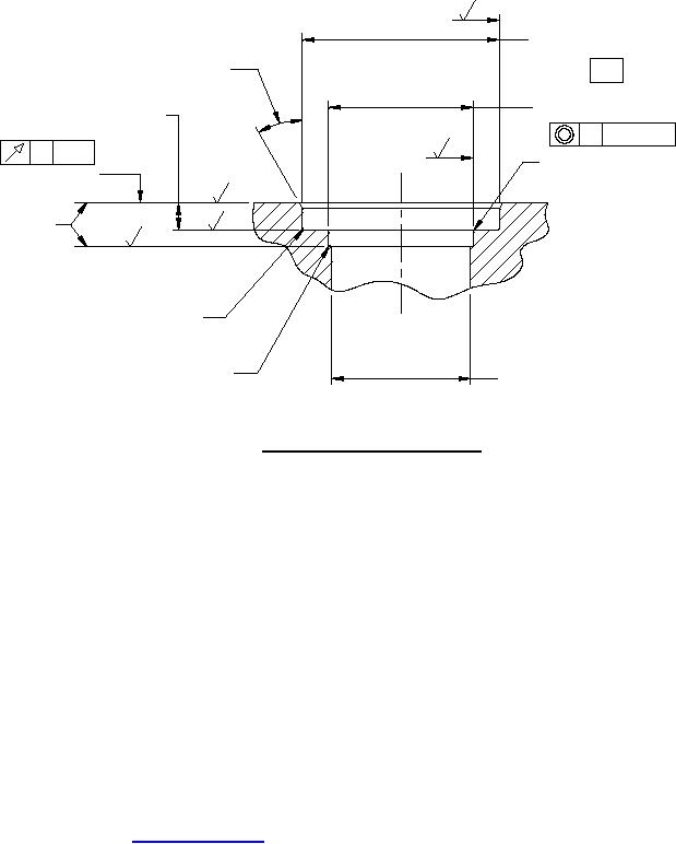
FIGURE 4. Porting details for mating flanges.
CHANGES FROM PREVIOUS ISSUE. Marginal notations are not used in this revision to identify changes with
respect to the previous issue due to the extent of the changes.
Custodians:
Preparing activity:
Navy SH
Navy SH
Air Force 99
(Project 4330-2013-012)
Review activities:
Air Force 84
DLA CC
NOTE: The activities listed above were interested in this document as of the date of this document. Since
organizations and responsibilities can change, you should verify the currency of the information above using the
ASSIST Online database at https://assist.dla.mil.
6
For Parts Inquires submit RFQ to Parts Hangar, Inc.
© Copyright 2015 Integrated Publishing, Inc.
A Service Disabled Veteran Owned Small Business