MIL-DTL-24402/2A
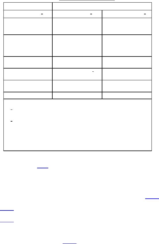
TABLE I. Cross reference of part numbers.
New part numbers
Old part numbers
(Fatigue rated) 1/
(Fatigue rated) 2/
(Non-fatigue rated) 2/
M24402/2NS
M24402-2N-BF-3
M24402-2N-BF-0
Right-hand outlet
(Rev. D and Earlier)
M24402/2NL
M24402-2N-BF-3
M24402-2N-BF-0
Left-hand outlet
Left-hand outlet
(Rev. D and Earlier)
(configuration not
qualified but exists)
M24402/2ND
M24402-2N-BF-3
(Rev. D, Amendment 1)
M24402-2R-BF-3 1/
M24402/2RS
M24402-2R-BF-0
Right-hand outlet
Right-hand outlet
M24402/2RD
M24402-2R-BF-3
(Rev. D, Amendment 1)
M24402/2RL
NOTES:
1/
If a differential pressure indicator is to be acquired with the filter assembly,
add the appropriate indicator dash number suffix from MIL-DTL-24402/5.
2/
Add E, G, or M depending on the form of differential pressure indicator
acquired with the filter assembly, as follows:
E
-
Electrical with mechanical pop-up indicator.
G
-
Gauge type indicator.
M
-
Mechanical pop-up indicator.
SUBSTITUTION OF ASSEMBLIES. Assemblies with new part numbers may be substituted for all assemblies
with old part numbers as shown in table I. Only assemblies with old part numbers that are fatigue rated may be
substituted for assemblies with new part numbers. Unless prevented by the thickness of the blind flange, the fatigue
rated assemblies with left and right dual outlet ports may be substituted for either left or right hand outlet port
assemblies.
REQUIREMENTS.
a.
Configuration. The filter assemblies shall meet the dimensional requirements shown on figure 1.
(1) Type N assemblies. Type N filter assemblies shall be in accordance with the schematic shown on
(2) Type R assemblies. Type R filter assemblies shall be in accordance with the schematic shown on
figure 3. Type R assemblies shall be similar to Type N assemblies except that they shall include a
bypass relief valve which will automatically bypass fluid around the filter elements when a specified
differential pressure is reached.
(3) Inlet and outlet ports. The inlet and outlet ports of the filter assemblies shall be in accordance with the
porting detail dimensions shown on figure 4. For assemblies with two outlet ports, a blind flange in
accordance with MIL-DTL-24704 and MIL-F-24704/4 shall be installed on the specified port utilizing
an insert sleeve in accordance with MIL-DTL-24704 and MIL-F-24704/5.
2
For Parts Inquires submit RFQ to Parts Hangar, Inc.
© Copyright 2015 Integrated Publishing, Inc.
A Service Disabled Veteran Owned Small Business