MIL-DTL-24402/3A(SH)
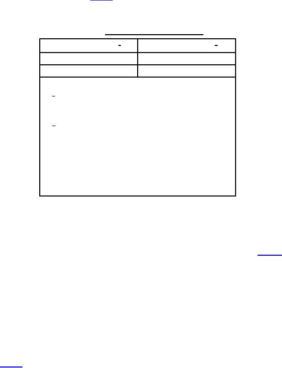
PART NUMBER CROSS REFERENCE. Table I provides a cross reference between old (MIL-F-24402D and
earlier) and new part numbers.
TABLE I. Cross reference of part numbers.
New part numbers 1/
Old part numbers 2/
M24402/3NB
M24402-3N-BF-0
M24402/3RB
M24402-3R-BF-0
NOTES:
1/
If a differential pressure indicator is to be acquired
with the filter assembly, add the appropriate indicator
dash number suffix from MIL-DTL-24402/5.
2/
Add E, G, or M depending on the form of differential
pressure indicator acquired with the filter assembly,
as follows:
E
-
Electrical with mechanical pop-up
indicator.
G
-
Gauge type indicator.
M
-
Mechanical pop-up indicator.
SUBSTITUTION OF ASSEMBLIES. Assemblies with corresponding old and new part numbers may be used
interchangeably provided the correct differential pressure indicator is used.
REQUIREMENTS.
a.
Configuration. The filter assemblies shall meet the dimensional requirements shown on figure 1.
(1) Construction requirements. Filter assemblies shall be constructed in accordance with UG of the ASME
Boiler and Pressure Vessel Code, Section VIII. Failure of any one bolt or locking element in the head
closure shall not result in the failure of other elements and the release of the closure or parts of the
closure. The closure shall permit visual external observation to ensure that the holding elements are in
good condition and are in full engagement when the closure is in the closed position.
b.
Maximum rated operating pressure. The filter assemblies shall have a maximum rated operating pressure
of 400 lb/inē.
c.
Rated flow capacity. The filter assemblies shall have a rated flow capacity of 150 gallons per minute.
d.
Performance.
(1) Bypass relief requirements. Type R assemblies shall have bypass relief valve settings as specified in
table II.
2
For Parts Inquires submit RFQ to Parts Hangar, Inc.
© Copyright 2015 Integrated Publishing, Inc.
A Service Disabled Veteran Owned Small Business